.jpg)
Case Analysis
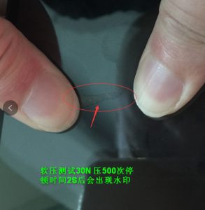
Framed project with watermark and heavy pressure reporting
In some low-end projects, a frame bonding process is used, which involves bonding the touch module and the display module together with foam adhesive. In addition to being prone to dust accumulation during use, this frame bonding structure can also cause watermarks when pressed and issues such as automatic touch point reporting after pressing.

For some 1.0mm narrow bezel display modules paired with narrow bezel touch modules, issues such as watermarks or pressure-based callouts are common. To address these issues, we recommend optimizing the following aspects:
| Serial Number | Risk level | Improvement measures |
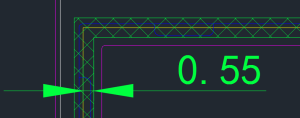
| 1 | High | The overlap width between the foam adhesive and the polarizer on the display module on one side must be ≥0.5mm. The gap between the polarizer and the LCD outline should be controlled at 0.1±0.1mm and machine-applied. Oil sand or fine sand should be used to apply the polarizer to provide anti-adhesion capability.
|
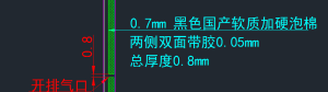
| 2 | Middle | For foam adhesive, choose rigid foam with a thickness of 0.7mm before compression and 0.4-0.6mm after compression. Make beveled or Z-shaped openings on the side or bottom edge of the foam adhesive and conduct a dust test. For double-sided adhesive, choose Crown 7972TB black glue to avoid white edges in the 45° visible area (this is because transparent double-sided adhesive reflects light at the edges, so it was changed to high-adhesion black glue).
|
| 3 | Middle | A sufficiently large gap must be maintained between the backlight surface of the display module and the casing, and the conductive sponge covering the backlight surface must be replaced with a soft, fluffy material to prevent the backlight surface from being squeezed, which would reduce the gap between the LCM and TP, resulting in watermarks or pixelation. |
| 4 | High | Misalignment between the display module and the touch module causes insufficient overlap between the foam adhesive and the polarizer on the display module, easily compressing the foam adhesive. To address this, fully automated lamination equipment can be used to eliminate the pressure-holding process, ensuring CCD alignment and improving the lamination accuracy between the display and touch modules. Foam adhesive application requires equipment or fixtures to guarantee an accuracy of ±0.1 mm. |
| 5 | Middle | The casing uses a dispensing process. Excessive glue can cause it to seep into and compress the foam, leading to deformation. The width of the foam adhesive can be controlled to 0.8-0.85mm to increase the gap between the dispensing path and the foam adhesive. |
| 6 | Low | For GF structure touch modules, the touch IC should preferably use the base 6540. The frame-mount process can be changed to a full lamination process. The thickness of the OCA in full lamination needs to be ≥0.175 to avoid interference from the display module in the GF structure touch module. However, full lamination is more expensive than frame-mount. |