Nullam dignissim, ante scelerisque the is euismod fermentum odio sem semper the is erat, a feugiat leo urna eget eros. Duis Aenean a imperdiet risus.
Nullam dignissim, ante scelerisque the is euismod fermentum odio sem semper the is erat, a feugiat leo urna eget eros. Duis Aenean a imperdiet risus.
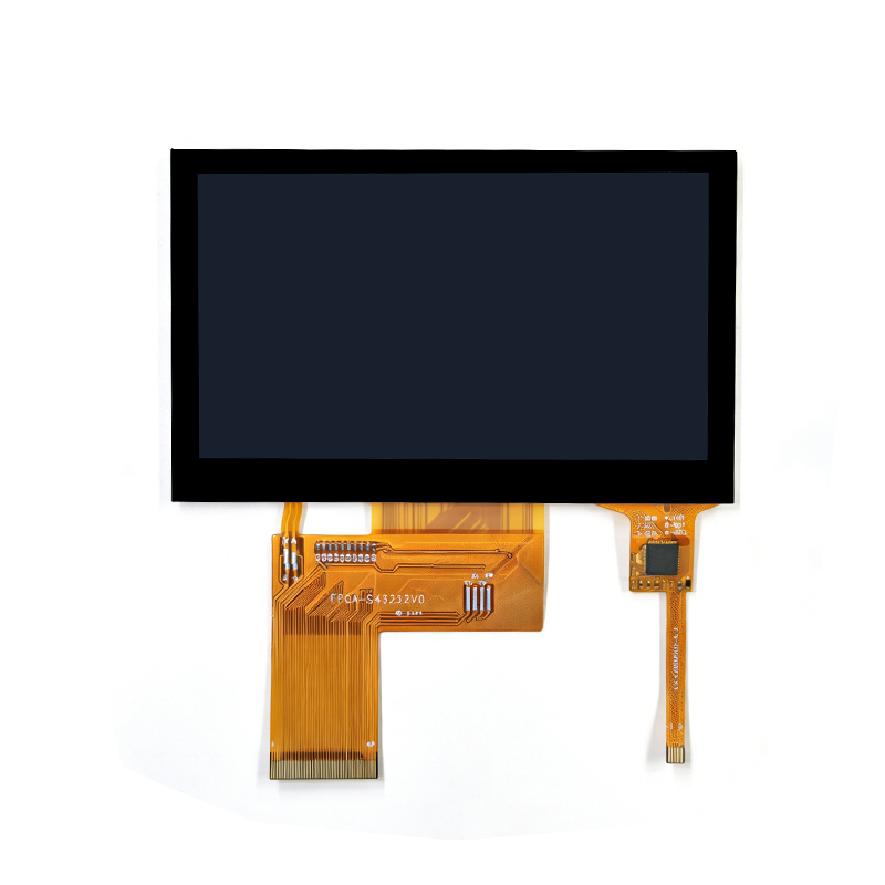 4.3-inch display assembly, LCD screen assembly for industrial instruments and meters
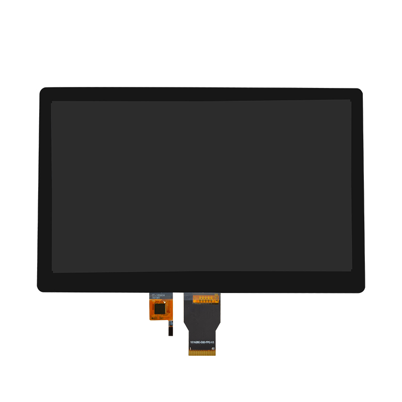 10-inch display assembly, touch screen assembly for industrial HMI human-machine interface
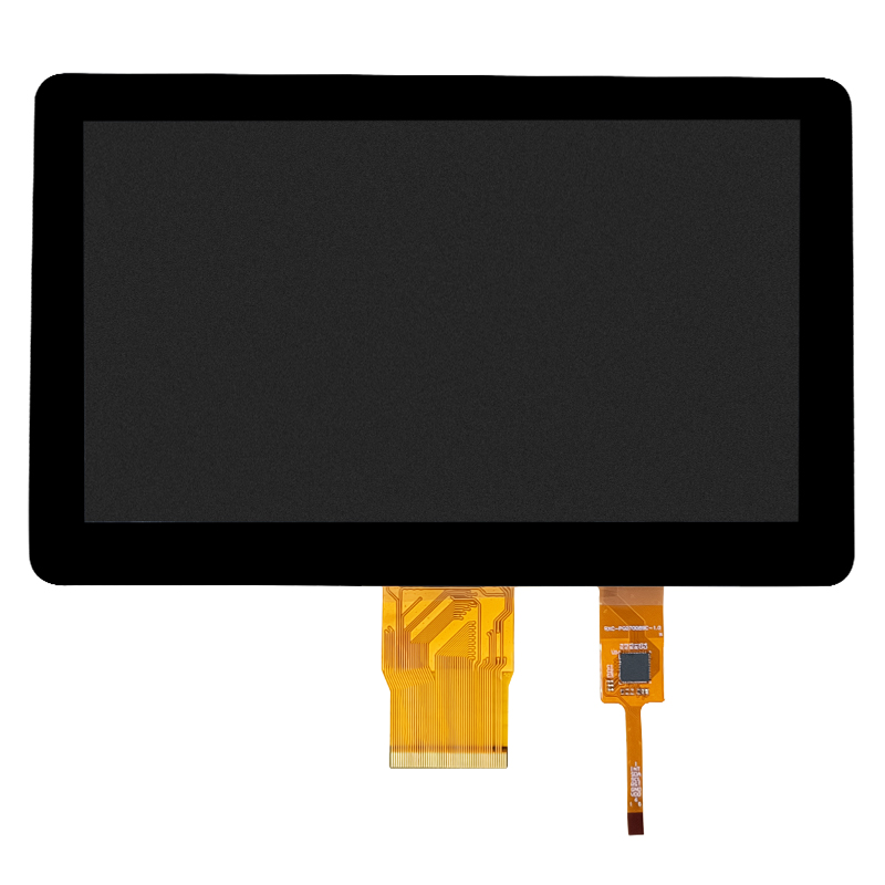 7-inch display assembly, automotive & industrial touch screen assembly, high-definition & high-brightness
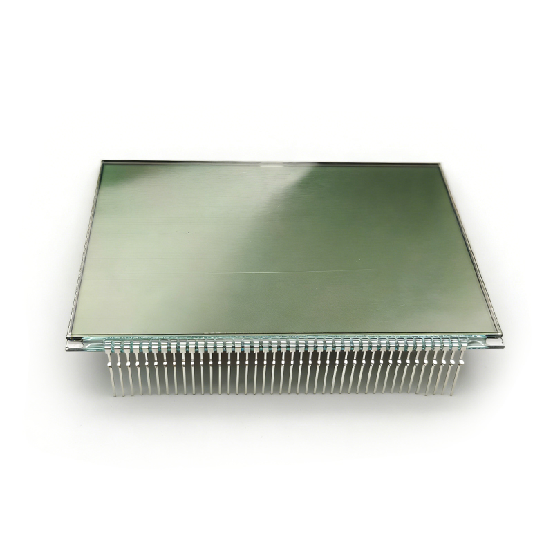 Dual-row pin segment code LCD screen, low-power display panel for industrial equipmentDual-row pin segment code LCD screen, low-power display panel for industrial equipment
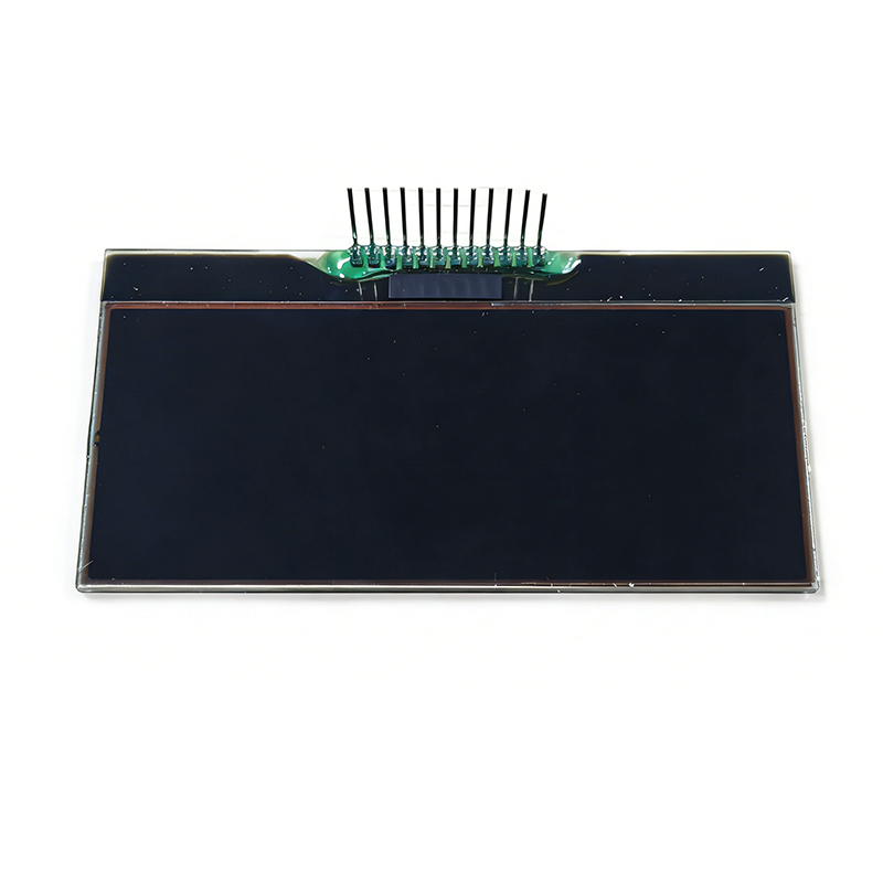 COG dot matrix pin-type black and white LCD screen, display for industrial instruments and meters
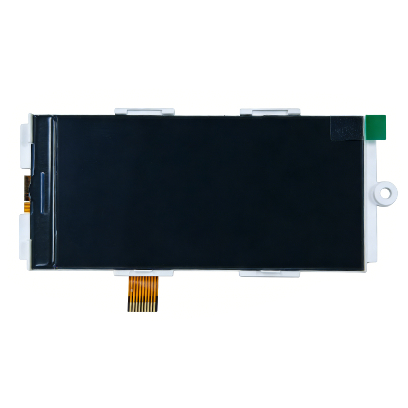 Narrow and long strip TFT color display assembly, industrial equipment strip LCD screen
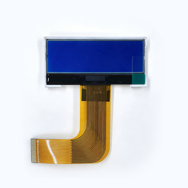 Small-size COG blue-background black-and-white LCD screen, segment code display for instruments and meters
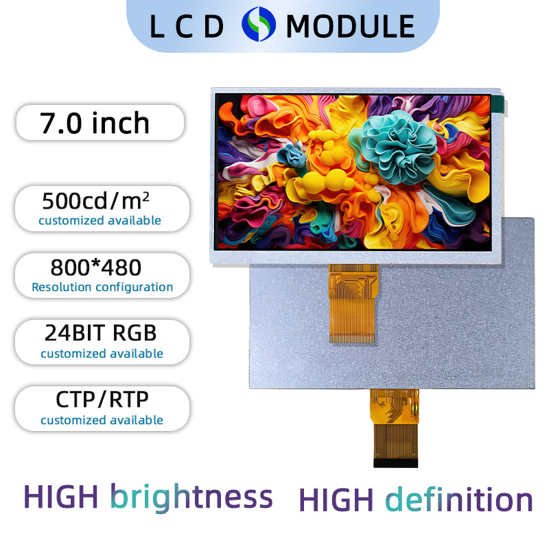 7-inch high-definition TFT LCD display, 800×480 resolution, 24-bit RGB interface, 500 nits brightness
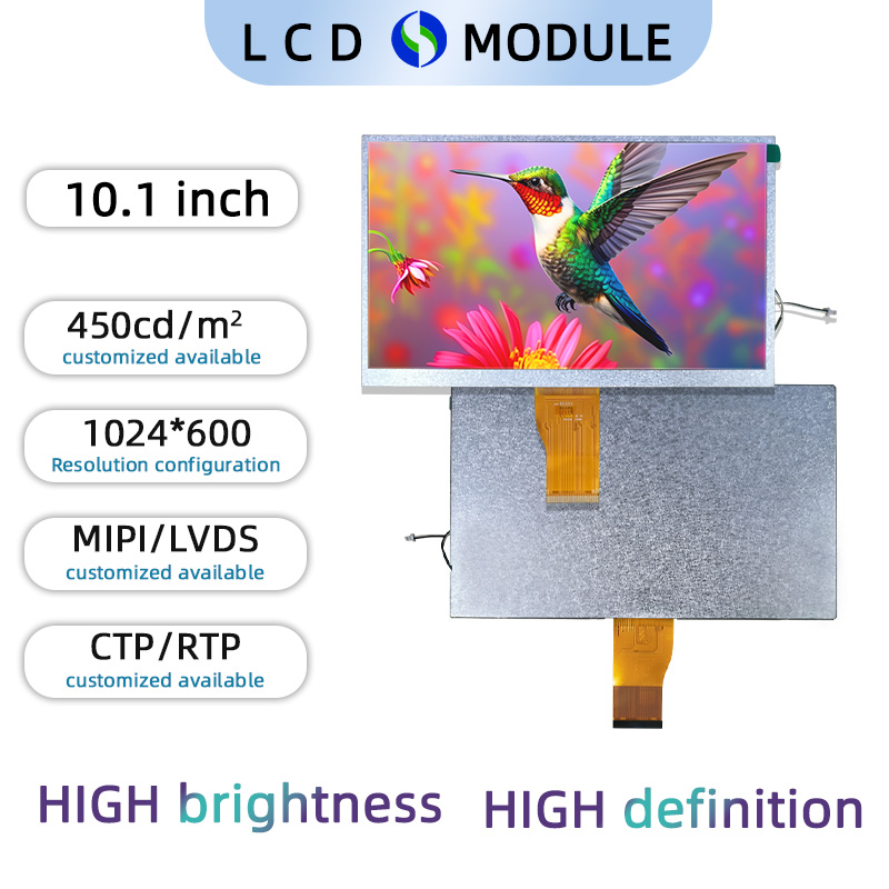 10.1-inch LCD display, 450 nits brightness, 1024×600 resolution, MIPI interface
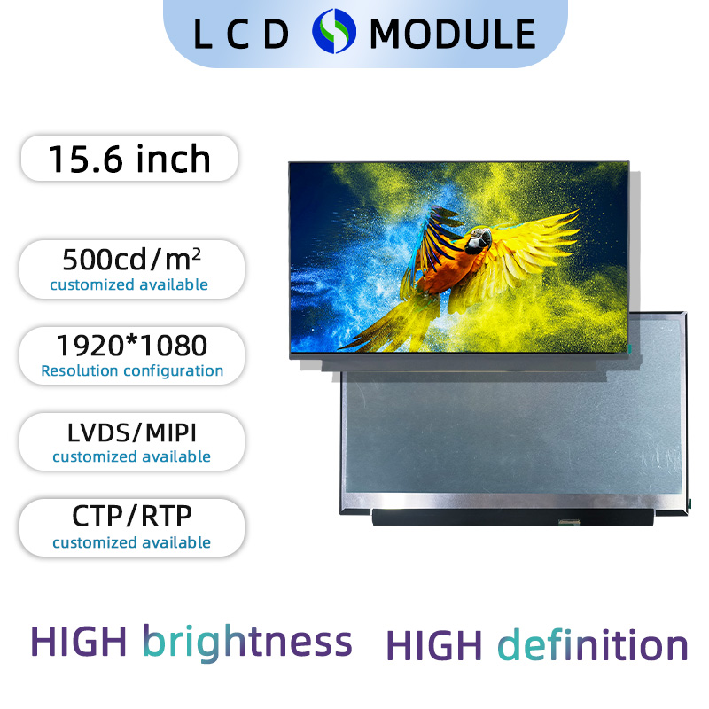 15.6-inch LCD display with 1920×1080 high-definition resolution, 500 nits brightness, LVDS interface
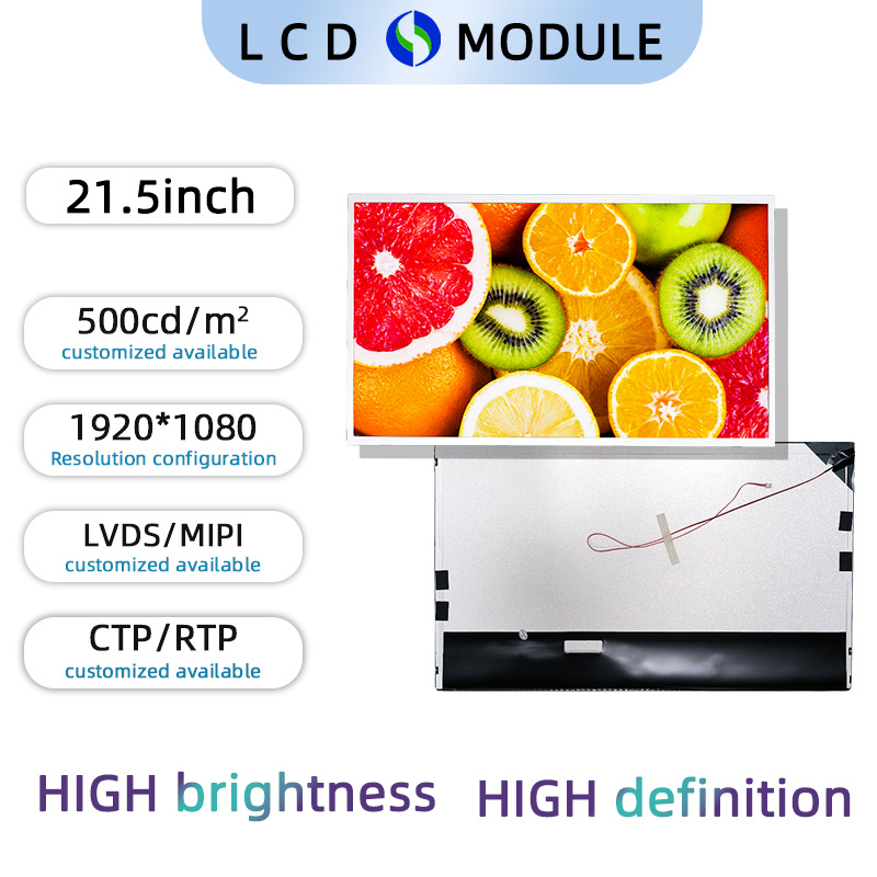 21.5-inch LCD display, 1920×1080 high-definition resolution, 500 nits brightness, LVDS interface
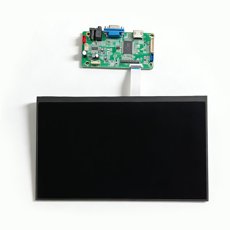 11.6-inch TFT LCD display assembly with driver board, industrial control display module
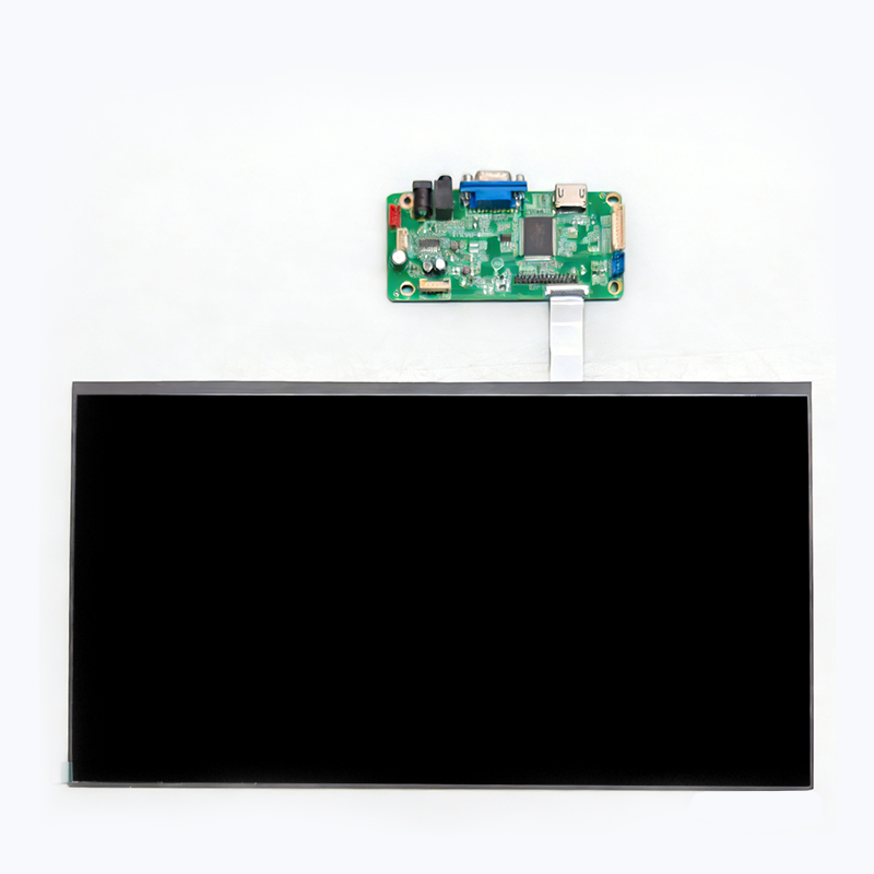 15.6-inch industrial-grade LCD display solution, integrated screen + driver board, supports multi-signal input4.3-inch display assembly, LCD screen assembly for industrial instruments and meters10-inch display assembly, touch screen assembly for industrial HMI human-machine interface7-inch display assembly, automotive & industrial touch screen assembly, high-definition & high-brightness

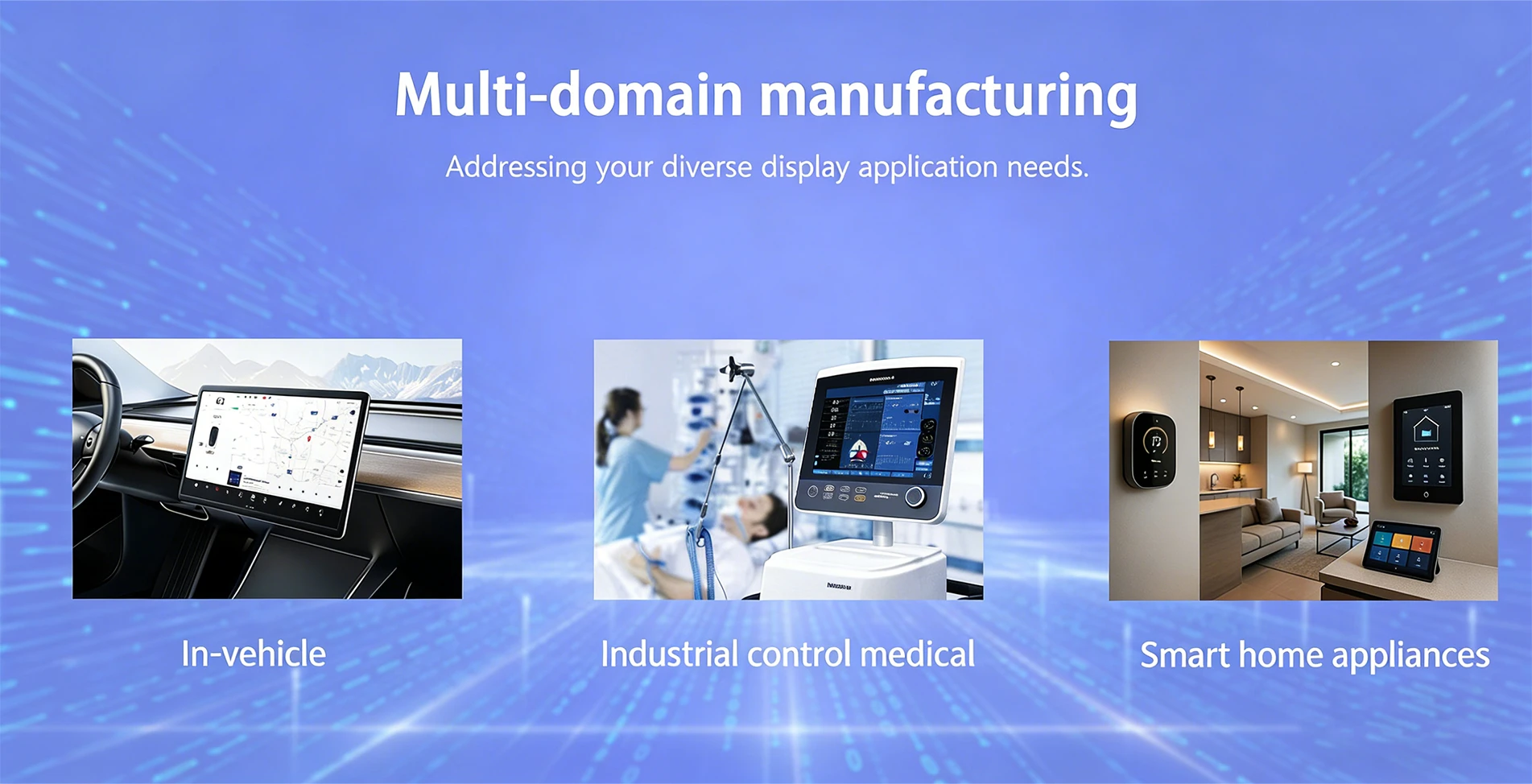
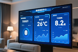
Industrial control and medical products impose the most stringent requirements on component quality, demanding stable product lifetime and consistent supply specifications, which pose significant challenges for display screens. Therefore, during the development phase, we have identified and selected more reliable supply brands. Another challenge lies in anti-static requirements, where we have extensive experience in enhancing protection for ICs and FPCs during development and design.
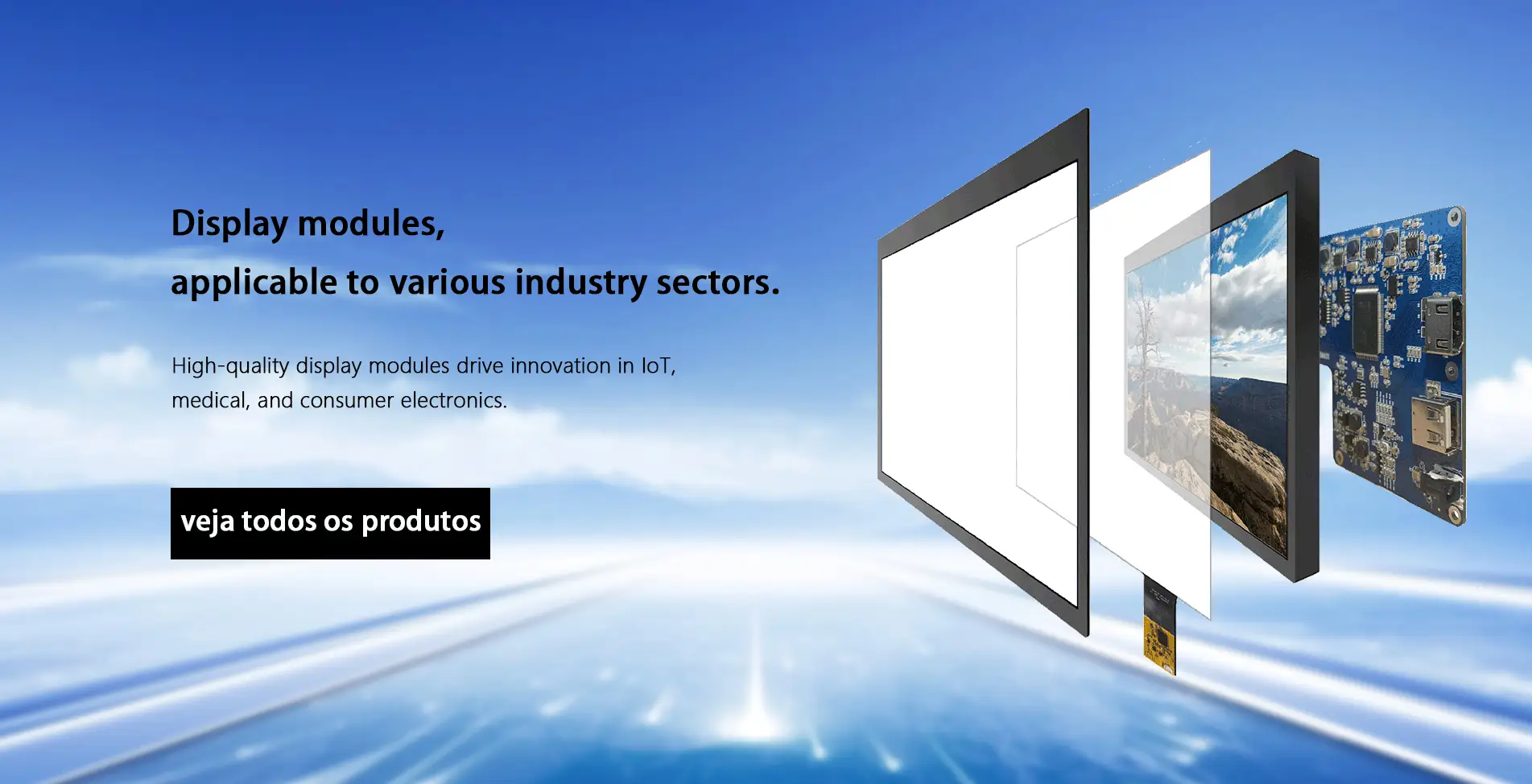
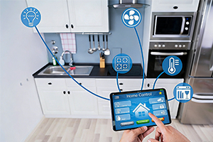
The Internet of Things has become a new trend in modern product logistics methods, encompassing functional requirements such as tracking, storage, and recording. To address these diverse scenarios, there are varying compatibility needs for display methods and sizes. We offer both monochrome and full-color display modules, along with matching driver solutions, ensuring that we can provide customers with suitable display design recommendations.
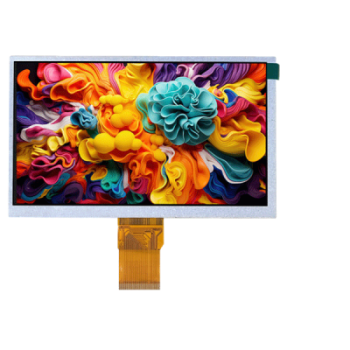
Based on the usage environment of customer products, the selection of key materials (such as glass substrates, polarizers, etc.) ensures more stable display performance under greater temperature variations. Additionally, methods like OCA lamination can be employed for integrating touchscreens, enhancing moisture resistance for displays and extending product lifespan and durability.
.jpg)
Case Analysis Solution for improving foreign objects in the backlight of TFT display modules In the composition of a TFT module, the backlight is a very important component. It emits light through LEDs, and the light guide plate converts the point light source into a surface light source. In order to achieve better uniformity and higher brightness, films such as brightness enhancement films and reflective films are usually added. In LCM module manufacturing plants, backlights have the highest defect rate and are the most difficult to improve. The most common problem in backlight assembly is foreign matter in the backlight. Common backlight foreign matter problems are divided into two types: foreign matter in the assembly of the backlight and the lower polarizer, and foreign matter inside the backlight film. Solution for improving assembly foreign matter between backlight and lower polarizer: Serial Number Risk level Improvement measures 1 High Each blister pack with backlighting needs to be covered with a large protective film to prevent dust. 2 Low Backlit incoming material inspection adds ion wind snake blowing to prevent dust falling. 3 Middle Daily cleaning of the backlight assembly machine: Wipe the conveyor belt with a lint-free cloth and pure water; clean the brushes under the skin with a vacuum cleaner; wipe the film-peeling platform and film-peeling rollers with a lint-free cloth and alcohol to remove residual adhesive; clean the dust from the air pipes and wiring surfaces inside the equipment with a vacuum cleaner; and wipe hard-to-reach corners with a lint-free cloth and alcohol. 4 High Humidification is added inside the backlight assembly machine to control the humidity at 70%. 5 High The nine-square grid analysis area is used to adjust the initial angle and area of the ion wind snake according to each project to ensure that the entire backlight can be blown. FOG film should be cleaned of dirt and grime on small surfaces with alcohol before being uploaded. 6 Middle The viscosity of the backlight black adhesive is adjusted based on the dyne value of the lower polarizer surface. Too low a viscosity allows dust to easily enter, while too high a viscosity causes yellowing at the edges of the LCM display. For lenses with a dyne value ≤ 22, the backlight black adhesive viscosity is 1600; for lenses with a dyne value > 22, the corresponding backlight black adhesive viscosity is 850, and for the optical element, it is 500 for easy disassembly. 7 Middle The upper brightening material should be made of anti-small ball material to avoid scratches and white marks caused by foreign objects between it and the lower polarizer. 8 High The key point regarding the gap between the backlight and the housing of the LCM is to confirm the length, width, and height gaps between the components and the housing after the FPC is bonded to the backlight. The length, width, and height gaps should all be ≥0.5mm. Adjust the gaps in each direction appropriately based on the housing deformation and the offset dimensions of the FPC bonding. The following are solutions to improve the problem of foreign matter inside the backlight film: Serial Number Risk level Improvement measures 1 High Backlight film materials should be selected based on their compressive strength, resistance to microsphere brightening, and resistance to diffusion of soft particles in high-haze conditions. Silver has better compressive strength than white reflector. 2 High Cleanliness control of all components within the backlight supplier: Vibration of the glue frame for 30 minutes at 50Hz; ultrasonic cleaning of the glue frame for 12 minutes; using utility knife blades instead of round blades for slitting to ensure sharpness and prevent burrs; replacing the blade every 3 rolls; using black glue to clean the slitting material; applying dust pads or white tape to the sides before production, followed by freezing at -10℃ for 2 hours to reduce static electricity and identify components; humidifying the backlight lamination equipment to maintain 70% humidity; vacuum adsorption and luminescence rotation inspection; after backlight assembly, all components undergo continuous vibrating at 180-220 rpm for 2 hours; and a full vacuum adsorption and luminescence rotation inspection. 3 High Establish a comparative library of foreign matter for spectral analysis of different models, and identify the source of foreign matter by region, layer, spectrum, and composition. 4 High LCM manufacturers conduct a series of inspections on incoming backlight materials, including a running vibration test at 180-220 rpm for 2 hours, a vacuum adsorption and light-emitting rotation inspection, and an IQC (Independent Quality Control) spot check at 70°C for 2 hours to confirm whether the backlight film material is arching. Improving LCM backlight foreign matter is a continuous and gradual process, and the root causes of problems will vary from project to project and batch to batch. Further investigation and confirmation must be carried out step by step according to the improvement plan above. Spectral analysis and comparison with the foreign matter library is a very useful tool and method for analyzing foreign matter white spot defects. Foreign matter lint defects in the touch film assembly can be analyzed in the same way as above.
.jpg)
.jpg)
Case Analysis Framed project with watermark and heavy pressure reporting In some low-end projects, a frame bonding process is used, which involves bonding the touch module and the display module together with foam adhesive. In addition to being prone to dust accumulation during use, this frame bonding structure can also cause watermarks when pressed and issues such as automatic touch point reporting after pressing. For some 1.0mm narrow bezel display modules paired with narrow bezel touch modules, issues such as watermarks or pressure-based callouts are common. To address these issues, we recommend optimizing the following aspects: Serial Number Risk level Improvement measures 1 High The overlap width between the foam adhesive and the polarizer on the display module on one side must be ≥0.5mm. The gap between the polarizer and the LCD outline should be controlled at 0.1±0.1mm and machine-applied. Oil sand or fine sand should be used to apply the polarizer to provide anti-adhesion capability. 2 Middle For foam adhesive, choose rigid foam with a thickness of 0.7mm before compression and 0.4-0.6mm after compression. Make beveled or Z-shaped openings on the side or bottom edge of the foam adhesive and conduct a dust test. For double-sided adhesive, choose Crown 7972TB black glue to avoid white edges in the 45° visible area (this is because transparent double-sided adhesive reflects light at the edges, so it was changed to high-adhesion black glue). 3 Middle A sufficiently large gap must be maintained between the backlight surface of the display module and the casing, and the conductive sponge covering the backlight surface must be replaced with a soft, fluffy material to prevent the backlight surface from being squeezed, which would reduce the gap between the LCM and TP, resulting in watermarks or pixelation. 4 High Misalignment between the display module and the touch module causes insufficient overlap between the foam adhesive and the polarizer on the display module, easily compressing the foam adhesive. To address this, fully automated lamination equipment can be used to eliminate the pressure-holding process, ensuring CCD alignment and improving the lamination accuracy between the display and touch modules. Foam adhesive application requires equipment or fixtures to guarantee an accuracy of ±0.1 mm. 5 Middle The casing uses a dispensing process. Excessive glue can cause it to seep into and compress the foam, leading to deformation. The width of the foam adhesive can be controlled to 0.8-0.85mm to increase the gap between the dispensing path and the foam adhesive. 6 Low For GF structure touch modules, the touch IC should preferably use the base 6540. The frame-mount process can be changed to a full lamination process. The thickness of the OCA in full lamination needs to be ≥0.175 to avoid interference from the display module in the GF structure touch module. However, full lamination is more expensive than frame-mount.
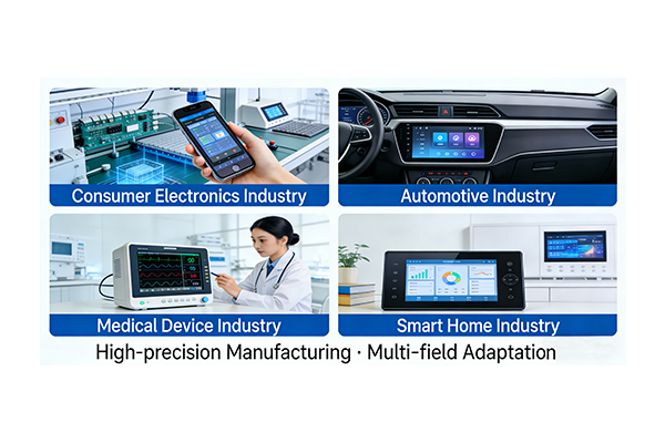
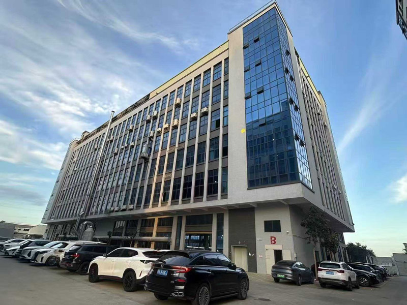
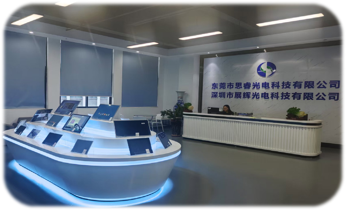
Dongguan SR Optoelectronics Technology Co., LTD., established in 2021, primarily researches and manufactures various small-to-medium-sized LCD display modules, including monochrome modules (LCM) and full-color modules (TFT). We can provide standard or customized products to meet diverse customer needs. Our factory covers an area of 3200 square meters and has four fully automated production lines. We currently employ nearly 100 people and have a monthly production capacity of 80,000 units. Our products cover a wide range of markets, including home appliances, instruments, smart wearables, IoT, industrial control and medical devices, and automotive applications. Our company and factory management personnel have over 10 years of experience in the display module industry. Throughout our development, we have cultivated experienced quality and production personnel and established a stable supply chain system. Building on our past achievements and striving for excellence, we adhere to a steady and pragmatic approach, working with our customers for mutual benefit and success!
Factory Area
Employ
Production lines
Industry Experience